Raster-Scan System In Computer Graphics
Interactive
raster graphics systems typically employ several processing units. In
addition to the Central Processing Unit (CPU), a special-purpose processor,
called the video controller or display controller, is used to control
the operation of the display device.
The raster scan system is well-suited for the realistic display of scenes
containing shading and color patterns.
A raster-scan
graphics system performs the following sequence of operations (figure 1.11):
Architecture & Working of Raster Scan System
The raster
scan systems are based on the use of a Cartesian coordinate system. Each
point is represented by x and y coordinates, where the value of x-increases from
left to right and y from top to bottom.
The Raster
Scan System is also called Point Plotting Technique. In the Raster
Scan System at the end of each scan line, the electron beam returns to
the left side of the screen to begin displayers the next line, this return to
the left of the screen after refreshing each scan line is called horizontal
retrace and at the end of each frame the electron beam returns to the top
corner of the screen to begin the next frame, this is called vertical retrace.
Track of a refresh cycle. Suppose refresh rate is required as 60HZ. One cycle
is completed in 1/60 sec.
Normally,
refreshing on raster scan displays is carried out at the rate of 60 to
75 frames per second, although some systems are designed for higher refresh
rates. Sometimes, refresh rates are described in units of cycles per
second, or Hertz (Hz), where a cycle corresponds to one frame. Using these
units, we would describe a refresh rate of 60 frames per second as simply 60
Hz.
In a
simple black and white system, the cache screen point is either on or off, so only
one bit per pixel is needed to control the intensity of screen positions. For a
bit-level system, a bit value of 1 indicates that the electron beam is to be
turned on at that position, and a value of 0 indicates that the beam intensity
is to be off. Additional bits are needed when color and intensity variations
can be displayed. Up to 24 bits per pixel are included in high-quality systems,
which can require several megabytes of storage for the frame buffer, depending
on the resolution of the system. A system with 24 bits per pixel and a screen
resolution of 1024 by 1024 requires (1024 x 1024) x 24)/8 = 3 MB storage for
the frame buffer.
On a black and white system with one bit per pixel, the
frame buffer is commonly called a bitmap. For systems with multiple bits per pixel, the
frame buffer is often referred to as a pixmap.
Refreshing
on raster-scan displays is carried out at the rate of 60 to 80 frames per
second, although some systems are designed for higher refresh rates. Sometimes,
refresh rates are described in units of cycles per second, or Hertz (Hz), where
a cycle corresponds to one frame.
Raster-Scan Display Processor
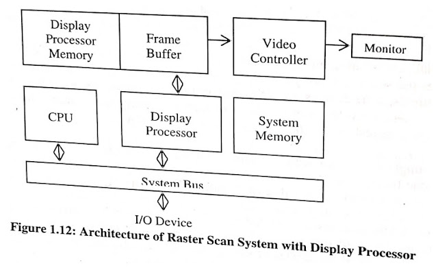
The
architecture of raster Scan with display processor is shown in figure 1.12. The
major task of a display processor is digitizing a picture definition given in
an application program into a set of pixel values for storage in the frame
buffer.
A
display processor for displaying data in one or more windows on a display
screen. The display processor divides a display screen into a plurality of
horizontal strips with each strip further subdivided into a plurality of tiles.
Each tile represents a portion of a window to be displayed on the screen. Each
tile is a tile defined by tile descriptors which include memory address locations
of data to be displayed in that tile.
The
descriptors need only be changed when the arrangement of the windows on the
screen is changed or when the mapping of any of the windows into the bit-map is
changed.
The
display processor of the present invention does not require a bit map frame
buffer to be utilized before displaying windowed data on a screen. Each
horizontal strip may be as thin as 1 pixel, which allows for the formation of
windows of irregular shapes, such as circles.
Display
Video Monitor Frame Processor Buffer Controller Memory System Memory Display
CPU Processor System Bus I/O Device Figure 1.12: Architecture of Raster Scan
System with Display Processor
Interlacing
On some
raster scan systems, each frame is displayed in two passes using an interlaced
refresh procedure. In the first pass, the beam sweeps (odd scan lines) across
every other scan line from top to bottom. Then after the vertical retrace, the
beam sweeps out the remaining (even scan lines).
The interlacing of the scan lines in this way allows us to see
the entire screen displayed in one-half the time it would have taken to sweep
across all the scan lines at once from top to bottom. Interlacing is
primarily used with slower refreshing rates.
Suppose
we have a refresh rate 30 Hz for a non-interlaced display, some flicker is
noticeable. But with interlacing, each of the two passes can be accomplished
1/60 of a second, which brings the refresh rate nearer to 60 frames per second
as illustrated in figures 1.13(a) and 1.13(b).
Advantages of Raster-Scan System
I) PC’s
all use raster scan and they can easily do color/shading.
2)
Printers are also raster scan devices and can give fairly *high-quality output.
3) A
raster graphic refresh memory architecture offering increased access speed.
Disadvantages of Raster-Scan System
1) The
minimal amount of information is large in raster.
2)
There is need to specify the dimensions in device-independent units.


